
SWTS ENET User Guide
SWTS Ethernet Bridge Users Guide
The Microtel SpaceWire Ethernet Bridge (SWEB) is a system which receives packet data via TCP Ethernet and forwards the data on Spacewire. Data packets received on Spacewire are forwarded on TCP Ethernet.
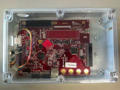
The SWEB consists of: clear top electronics box. Mini USB power cable with 120V convertor. Ethernet RJ45 connector Spacewire MDM 9 pin connector External grounding screw.
The clear top electronics provides easy observance of the circuit board LEDs. There are 2 yellow LEDs and 4 red. When the board is off and unplugged all LEDs are off.
End to end throughput for the device is ~1.5 MBPS. The Spacewire transmit data rate is programmable with rates up to 200 MBPS with default at 10 mbps.
An application software executable is provided which enables: Connecting to the SEB for transmit and receive. Generating test packets and sending to the SEB. Receiving and display of packets from the SEB.
SWTS Software
The program consists of six windows, "Root window", "Data Received", "Speed Test", "Commands", "SWTS Monitor" and "Controller". In order to use the SWTS application software, you must do an SVN checkout of the SWTS software repository (https://wush.net/svn/microtel/SWTS-ENET.). Once checked out, the latest SWTS application software will be located in: SWTS-ENET\SWTS_MASTER_release\w7_x64\QT5\SWTS_Master_1_5_0.exe. There are previous versions located in the QT4 folder, however the latest version should be used. To start the software, just double click SWTS_Master_1_5_0.exe.
Root Window
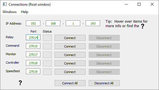
The root window allows you to individually connect to the different sockets on the SWTS ethernet board. Closing the root window closes the application. If you close one of the other windows, they can be brought back up from the "Windows" menu.
Data Received
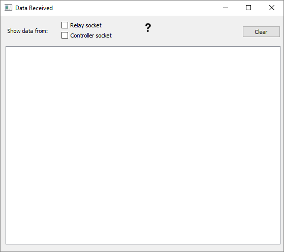
This window can be use to display any data received back by the GUI app. You may view data from either the relay socket or the controller socket. Make sure you are connected to the appropriate socket in the root window before attempting to view any data.
Speed Test
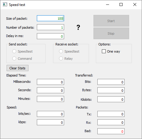
This window is used to conduct a speed test of the SWTS ethernet board. To conduct a speed test, first select which socket you want to send packets out of. Then, select which socket you want to receive packets on, then click "Start". Click "Stop" to end the test.
Results of speed test
Send Socket Receive Socket Loop back Result in kbps SWTS to SWTS Result in kbps
Speedtest Speedtest 164 110 Speedtest Relay 88 67 Command Speedtest 66 48 Command Relay 69 47
Commands
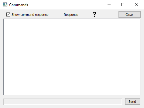
This is where you may enter SWTS commands that will be sent to the SWTS ethernet board. If the command is valid SWTS_OK response should be received.
SWTS Monitor
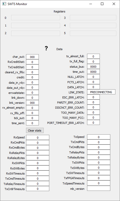
This window displays data about the SWTS ethernet board. All the data in this window is contained in a SWTS status packet that is sent once per second. The "Register" section shows the hex value of the six different registers. The "Data" section shows the data from the registers and displays each piece of data individually. The "Statistics" section shows the Rx and Tx values of the spacewire link along with some useful counts.
Controller
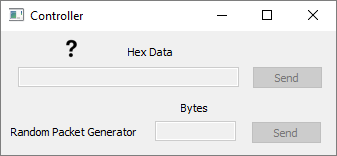
This window utilizes the controller socket. This can be used to send data to the SWTS ethernet, bypassing the command socket. Data is sent in binary form.
A loopback test connector is provided for easy setup and verification of operations.
In order to connect to the SWTS, your computer must be on the same subnet as the SWTS board. The IP of the SWTS board is 192.168.1.193, your computer must be on the 192.168.1.100 subnet. In Windows, open control panel, go to network and sharing center and select "change adapter settings" in the side bar. Right click on the local area network and select "internet protocol version 4" from the list. Change the ip to one on the 192.168.1.100 subnet and click "ok".
Commands and data packets are sent to the SEB via a command socket. Command and data are sent in ascii for simple operation. The commands are:
if (!strcmp(words.words[1], "PORTSPEED")) return SWTSOP_PORTSPEED;
PORTSPEED
This command shall configure the speed of the SpaceWire port. Command
Format: "SWTS PORTSPEED <portNum> <portSpeed>"
<portNum> is a required parameter. The format is ASCII decimal.
The value must be between „1‟ and „4‟.
<portSpeed> is a required parameter. The format is ASCII
decimal. The value represents the port Speed in Megahertz (MHz).
PORTUP This command shall cause the SWTSv2 to attempt to bring up
the port specified on the command line. Command Format: "SWTS PORTUP
<portNum>" <portNum> is a required parameter. The
format is ASCII decimal. The value must be between „1‟ and „4‟.
PORTDN
This command shall cause the SWTSv2 to bring down the port specified on
the command line. Command Format: "SWTS PORTDN <portNum>"
<portNum> is a required parameter. The format is ASCII decimal.
The value must be between „1‟ and „4‟.
RXRELAY2
This command behaves exactly the same as RXRELAY, except that it does
not strip the selected packets from the receive stream, it duplicates
them. Command Format: "SWTS RXRELAY2 <rt1>...<rtN>"
JWST-HDBK-003997 Revision Q 4-15 CHECK WITH JWST DATABASE AT:
https://ngin.jwst.nasa.gov/ TO VERIFY THAT THIS IS THE CORRECT VERSION
PRIOR TO USE. Use or disclosure of data contained on this page is
subject to the restriction(s) on the title page of this document.
rt1>..<rtN> value of Routing Byte(s) of packets to be stripped
from the received packet stream and relayed to the remote computer
system. The user may specify from 1 to 10 unique SpaceWire addresses for
relaying. The value of 0 will cause the SWTS to stop relaying all
packets. A value of „FF‟ will cause all received packets to be forwarded
to the relay socket. (Note: 'FF' will not work properly in applications
where the attached SpaceWire equipment can send data continuously at
more than a few Mbps) For high-speed applications use RXFILE to capture
data and analyze it after the fact
CLRCNTS
This command clears all status counts on the SWTSv2. Command Format:
return SWTSOP_ECLIPSECFG;
TXPKT
This command shall configure the SWTSv2 to transmit a single packet one
or more times. Command Format: "SWTS TXPKT <portNum> -p(s)
[-L] [<loopCnt>]" <portNum> is a required
parameter. The format is ASCII decimal. The value must be between „1‟
and „4‟, and indicates from which physical port the packet will be
transmitted. -p(s) is a required parameter. It denotes the beginning of
the packet definition. „-ps‟ shall cause a four octet sequence number to
be appended to the end of each packet. „-p‟ does not cause a sequence
number to be appended to the end of the packet. is a required parameter
set. It is essentially the packet to be transmitted represented as a
string of ASCII-hex bytes separated by spaces. The bytes shall be
transmitted onto the SpaceWire in the same order as they are entered on
the command line. [-L] is an optional parameter. It is used to include
a loop count with the packet definition. [<loopCnt.] is an optional
parameter that defines how may times to transmit the defined packet.
Command Result: The transmitter shall transmit the defined packet out
the specified port. If the --L option is used, the same packet shall be
transmitted <loopCnt> times. If the --L option is not present,
the packet shall be transmitted once.
Board Layout

Four discrete LEDs are installed on the board and can be used to display the status of the internal logic. These LEDs are attached as shown below and are lit by forcing the associated FPGA I/O pin to a logic '1' and are off when the pin is either low (0) or not driven.
LED Name Corresponding Board Label FPGA pin #
FPGA_GPIO_LED1 D1 J13 FPGA_GPIO_LED2 D2 K14 FPGA_GPIO_LED3 D4 U17 FPGA_GPIO_LED4 D5 U18
1 LED after power on 1 LED after program is loaded and running 1 LED for Command Socket connect 1 LED for Relay socket connect.
Development is using Xilinx ISE version 13.?
Signals brought to externals pins: DataRx => J5 PMOD1 P1 StrobeRx => J5 PMOD1 P2 DataTx => J5 PMOD1 P3 StrobeTx => J5 PMOD1 P4
Connector Pin Signal Name Board Pin
1 Din+ T6 2 Sin+ R7 3 Inner Shield GND 4 Sout- V5 5 Dout- P6 6 Din- V6 7 Sin- T7 8 Sout+ U5 9 Dout+ N5
Libraries/documents/LX16laoder
Eclipse Status Packet
SWTS Status Registers
::Once / second read and display registers 1,2 & 5.\
:
:   RxCreditStat =\> swts_reg2(29 to 31), 0 - 7\
:   TxCreditStat =\> swts_reg2(26 to 28), 0 - 7\
:   char_out =\> swts_reg1(0 to 9), display as hex\
:   cleared_rx_fifo =\> swts_reg2(25), 0 - 1\
:   credit =\> swts_reg2(24), 0 - 1\
:   data_in_rdy =\> swts_reg2(23), 0 - 1\
:   data_out_rdy =\> swts_reg2(22), 0 - 1\
:   errwaitstate =\> swts_reg2(19), 0 - 1\
:   link_down =\> swts_reg2(18), 0 - 1\
:   link_version =\> swts_reg2(10 to 17), 0 - ?\
:   rx_almost_empty =\>swts_reg2(9), 0 - 1\
:   rx_fifo_ff =\> swts_reg2(8), 0 - 1\
:   status_bus =\> swts_reg5(0 to 15), display in hex \-- breakout
    below\
:   tick_out =\> swts_reg2(6), 0 - 1\
:   time_out =\> swts_reg5(16 to 23), display in hex\
:   time_sent =\> swts_reg2(5), 0 - 1\
:   tx_almost_full =\> swts_reg2(4), 0 - 1\
:   tx_full_flag =\> swts_reg2(3) 0 - 1\
Register 5 STATUS_R(15) <= NULL_LATCH;"
STATUS_R(14) <= FCTS_LATCH;
STATUS_R(13) <= DATA_LATCH;
STATUS_R(10-12) <= LINK_STATE;
::::1 - ERROR RESET
:
:   2 - ERROR WAIT
:   3 - READY
:   4 - STARTED
:   5 - PRE CONNECTING
:   6 - CONNECTING
:   7 - RUN\
STATUS_R(9) <= ESC_ERR_LATCH;
STATUS_R(6-8) <= PARITY_ERR_COUNT(2); 0 - 7
STATUS_R(3-5) <= DISCNCT_ERR_COUNT(2); 0 - 7
STATUS_R(2) <= TOO_MANY_DATA;
STATUS_R(1) <= TOO_MANY_FCC;
STATUS_R(0) <= PORT_TIMEOUT_ERR_LATCH;\
The IP address of the board is 192.168.1.193.
SWTS Data Relay Socket
Connect to port 27014 for the SWTS Data Relay Socket. It works as defined in the SWTS User's Manual, section 4.3.3.
SWTS Command Socket
Connect to port 27015 for the SWTS Command Socket. It works as defined in the SWTS User's Manual, section 4.3.2. Not all SWTS commands are implemented, however. These are the implemented commands:
SWTS PORTUP SWTS PORTDN SWTS PORTSPEED SWTS RXRELAY3 SWTS TXPKT SWTS CLRCNTS
SpaceWire Controller Socket
Connect to port 27018 for the SpaceWire Controller Socket. This can be used for simple transmission of SpaceWire packets over Ethernet.
There are two kinds of packets that can be sent to the SpaceWire Controller Socket.
The first is a data packet. It contains an 8-octet header, followed by the raw bytes of a single SpaceWire packet. The first 4 octets of the header identify the packet type; they should all be 0. If an EEP packet need to be sent, those four octets should be 0x00 00 00 04 instead. The last 4 octets of the header should be the length of the SpaceWire packet, as an unsigned 32-bit integer. The SpaceWire packet should directly follow.
Updates must be requested by sending an Update Request. This should be four octets: 0x00 00 00 03.
When an Update Request is received by the board, it will respond with an Update Packet. An Update Packet has a 4-octet header, followed by a number of SpaceWire packets. The header contains the number of SpaceWire packets as an unsigned 32-bit integer. Each of the following SpaceWire packets are formatted with a 5-octet header followed by the raw SpaceWire packet data. The header starts with a 4-octet length field, which represents the number of bytes in the SpaceWire data as an unsigned 32-bit integer. The next octet is 0x00 if the packet was marked with EOP, and 0x01 if the packet was marked with EEP. It is then followed by the SpaceWire packet data. The SpaceWire packet data is immediately followed with the start of the next SpaceWire packet.
SEB Design Information
Implementation uses AVNET Xilinx Spartan-6 LX16 Evaluation Kit
Spacewire implementation based on GSFC Spacewire Link. Same IP core used in SWTS. Single Link with transmit data speed up to 200 mbps.
FPGA code developed in Xilink EDK versinon 13.2. Core is under project dslink. Microblaze interface is under project hw_design.
Microblaze processor implemented at 1.5 mbps. The board has 32 Mb x 16 (512 Mb) Micron LPDDR Mobile SDRAM component 128 Mb Numonyx Multi-I/O SPI Flash
XPS Etherlite core implemented for ethernet communications.
Microblaze flash bootloader implemented in FPGA. The bootloader is configured in wush.net SVN as SWTS_LX16_BSP and is version 67.
The Microblaze application code is stored in onboard flash memory and boots automatically when the board is powered on. The code provided reception of packet data via TCP/ethernet and forwarding on Spacewire, and Reception of packets on Spacewire nad forwarding on TCP/Ethernet. The current Microblaze code is configured under SVN as SWTS_LX16 and is version 103.
No Comments